The measurement of the transformation ratio is a very important factor when evaluating the conditions in which our transformer is located. What the transformation ratio tells us is the ratio of the primary coil voltage to the secondary coil voltage. These positions of the transformer work so that we have a voltage of 120V as a supply in our home, if we have a voltage in the medium voltage that do that in the low voltage we do not have 120V, we simply move it to the position of the transformer until we have 120V .
A simple example is if we have a transformer in which the primary voltage is 13200V and 120V in the secondary, our transformation ratio is calculated as follows:
\cfrac{13200}{120\times \sqrt{3}}=63.50
Which gives us as a result that our transformation ratio is 63.50.
It must also be taken into account that the transformation ratio can be calculated with the voltages, however, if we only calculate it with the voltages, we cannot know how many turns the transformer has in the coils, neither primary nor secondary. This is discussed because when we calculate the transformation ratio with a real transformer, all we have is the transformer data plate and the measuring equipment. Let’s go with one more example from real life.
Calculate the transformation ratio with the transformer plate
The transformer that we will see next has 5 positions, so we are going to calculate 5 transformation ratios and then compare those 5 calculations with the measurements.
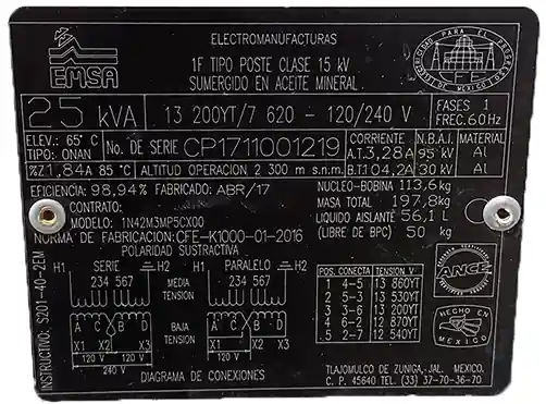
What interests us about the board is to see the type of transformer, which in this case is a star; and the voltage of the medium voltage that goes from phase to ground (this is to know what voltage is the one that we will use for the calculation) and the table that has in the lower right part:
| Position | Connect | Voltage |
| 1 | 4-5 | 13860YT |
| 2 | 5-3 | 13530YT |
| 3 | 3-6 | 13200YT |
| 4 | 6-2 | 12870YT |
| 5 | 2-7 | 12540YT |
Since the medium voltage goes from line to ground, then it has to be divided by the root of 3. The voltage of 13200V that we see on the board is a line-line voltage and since our transformer only has to connect one line to it, we divide by the root of 3 each voltage that appears on the board, which is what was written in Table 1 and at once we can divide between the voltage in low voltage from line to ground that this has to be 120V because it is the one that in the end they are delivering to our home.
The formula for the transformation ratio is as follows
\cfrac{\text{Voltage of each medium voltage position according to table 1}}{120V\times\sqrt{3}}| Pos. | Voltage L-L | Voltage L-T | Relation |
| 1 | 13860YT | \cfrac{13860}{\sqrt{3}} | 66.683 |
| 2 | 13530YT | \cfrac{13530}{\sqrt{3}} | 65.096 |
| 3 | 13200YT | \cfrac{13200}{\sqrt{3}} | 63.508 |
| 4 | 12870YT | \cfrac{12870}{\sqrt{3}} | 61.920 |
| 5 | 12540YT | \cfrac{12540}{\sqrt{3}} | 60.333 |
Measure the transformation ratio with DTR equipment (Digital Transformer Ratio)
Since we have our transformation ratio calculated, what it should give us in the measurement is a value as close as possible that does not exceed 5% difference between the measured and the theoretical. To start with the measurement we have our DTR equipment that comes with its connection diagram as shown in Figure 2.
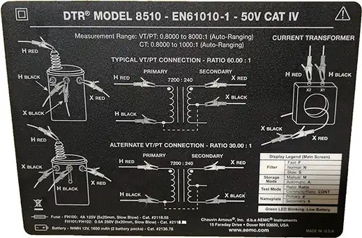
I am using the first diagram, except that in the diagram that comes with the equipment, the black clamp of the connection that goes to the medium voltage part is in the middle one, in X2 of the transformer. What we are going to do is disconnect the connection from X2 to the tank and we will connect the black clamp of the medium voltage part to the back of the transformer and we will connect the red clamp of the medium voltage part at the end where the cable goes of medium voltage.
Now, pay attention, with the low voltage part we will connect our black clamp to X2 of the transformer and we will connect our red clamp to X1. The diagram in Figure 2 shows that it must be connected to X3 of the transformer but the only detail that we will obtain is that when measuring the equipment it will give us a negative measurement. On the other hand, in the X1 it will be positive. I leave you homework on why it gives a negative measurement between X2 and X3.
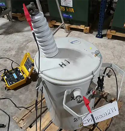
In Figure 3 we can see that we have connected our red medium voltage clamp to H1 of the transformer. We also see that in X1 and X2 there are the red and black clamps of the low voltage part respectively.
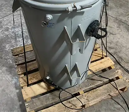
And on the back in Figure 4 we see that the black clamp of the medium voltage part is connected to the tank.
We placed our transformer in each of the positions and began to measure them one by one!

Figure 5. Transformer in position 1.
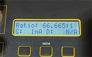
Figure 6. Measurement of the transformation ratio in position 1.

Figure 7. Transformer in position 2.
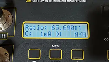
Figure 8. Measurement of the transformation ratio in position 2.

Figure 9. Transformer in position 3.
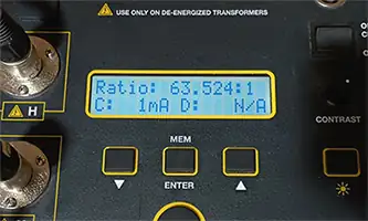
Figure 10. Measurement of the transformation ratio in position 3.

Figure 11. Transformer in position 4.
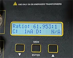
Figure 12. Measurement of the transformation ratio in position 4.

Figure 13. Transformer in position 5.
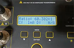
Figure 14. Measurement of the transformation ratio in position 5.
Perfect! The measurements are already done, now we can compare them with those calculated theoretically to see that they are within 5% of variation.
| Pos. | Theo. Ratio | Meas. Ratio | % |
| 1 | 66.683 | 66.665 | \sim 0 |
| 2 | 65.096 | 65.090 | \sim 0 |
| 3 | 63.508 | 63.524 | \sim 0 |
| 4 | 61.920 | 61.953 | \sim 0 |
| 5 | 60.333 | 60.382 | \sim 0 |
Conclusion of this transformation ratio test
The variation observed in Table 3 is almost zero, giving a value far removed from a value of 5%. So we can safely say that the transformer are in good condition.
If there is a very large variation, we can deduce that in one of the turns of a coil, or perhaps both, they are united. This happens when the load of the transformer is exceeded and so that it does not get worse like it explodes, it simply melted and joined in some turn. What this problem is going to do to us is that the voltage that it delivers to the outlet is not 120V, giving us problems with the voltage and with our electrical-electronic equipment.
Thank you for being here with us : )